Main
Main Site Map
 Blog
Blog Calendar
 Gallery
 Site Traffic
 Site Health
> /Daniel/MRoadster/Upgrades/AudiofactoryWiring.php
Speakers
| kick panels (left and right) | 5.25" |
| door panels (left and right) | 2" and 1" tweeters |
| rear (left and right) | 4" |
| subwoofer | dual voice coil 6.5" |
Factory amplifier wiring
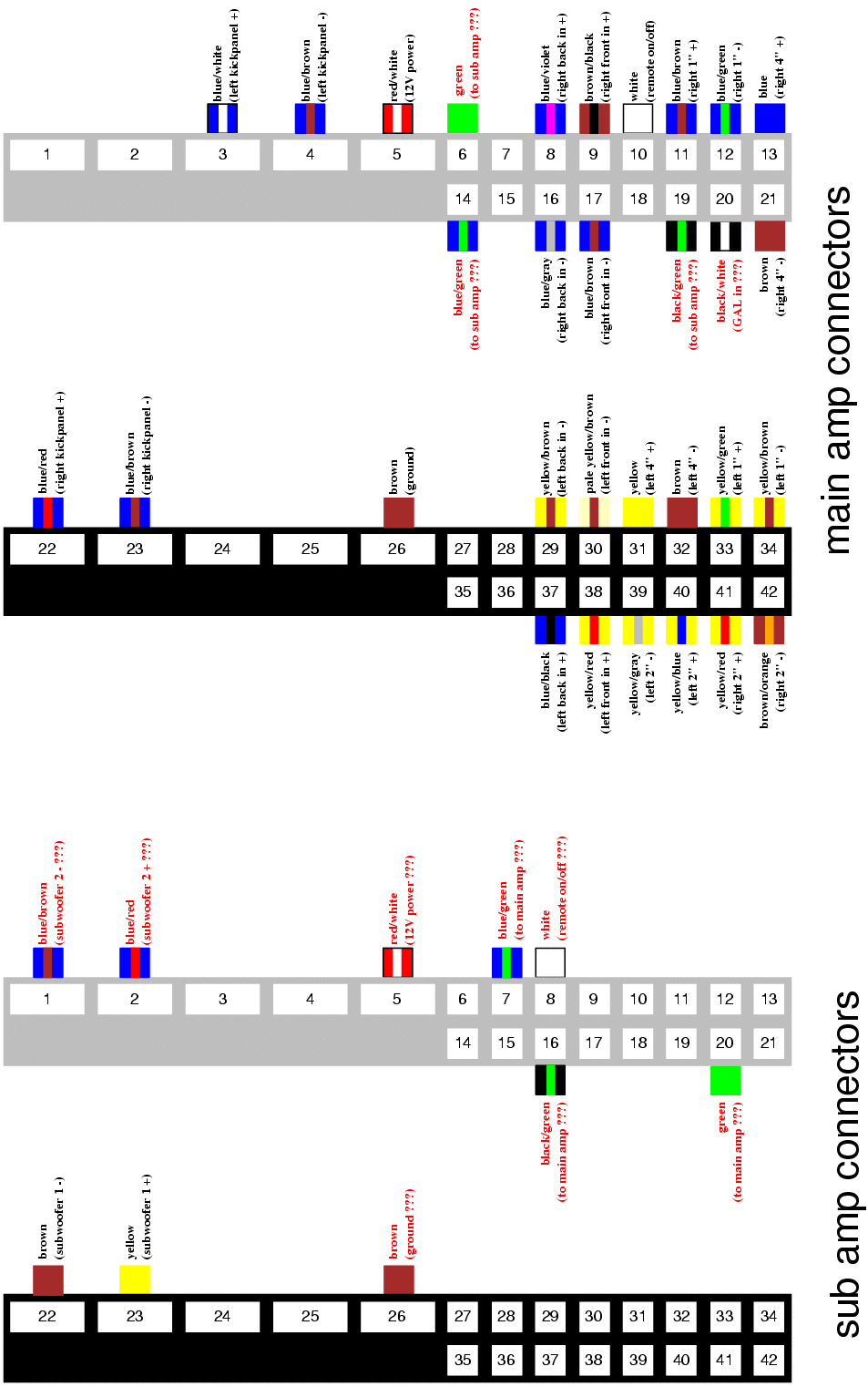
There are 2 amplifiers in the trunk. The main amplifier is behind the lump in the carpet on the passenger's side. The subwoofer amplifier is behind the carpet on the driver's side.Each amplifier has two 21-pin connectors (gray and black) housed in a black plastic jacket (to make a 42-pin connector). These connectors can be released from their plastic jacket using a small screwdriver (pry up the tab in the side, slide the connector out of the jacket). You'll then have 4 total connectors: one gray and one black for the main amp, and one gray and one black for the subwoofer amp.
The diagram below shows the wire colors for each occupied pin in the connectors. Wires with labels in black text have been functionally verified. Wires with labels in red text have not been functionally verified, and hence their functions are best guesses based on the old amplifier design. Click here for a copy in Postscript for printing.
Note that I don't intend to verify the remaining wires, because I am replacing the two amps with a single Alpine MRD-F752 5-channel amplifier (the whole point of the diagram: I need it while doing this work). However, I would assume that my guesses are all correct, and that the green wire is a common negative for left and right subwoofer channels, the blue/green wire is positive for one of the subwoofer channels and the black/green wire is positive for the other subwoofer channel. You don't need this information unless you intend to replace one of the amplifiers with an aftermarket amplifier but not the other. Also note that I replaced my subwoofer driver with a single voice coil Kicker driver, and hence don't need to verify the blue/brown and blue/red wires (but my guess should be correct).