 Main
Main Site Map
 Blog
Blog Calendar
 Gallery
 Site Traffic
 Site Health
M Roadster Audio Round 2 Diary
- June 22, 2008
-
Audio
There are no leaks with the new setup. Yay!I rewired the pump with AMP Universal Mate N Lok 3-pole connectors with wire and interface seals. If I spring a leak, it shouldn't affect the wiring (unlike the Molex connectors). The blue wire is the pump rpm output wire, which I ran into channel 4 of the Digital Doc 5 so I can see that the pump is running.
I think this concludes round 2 of the watercooling.
-
Audio
- June 17, 2008
-
Audio
I re-oriented the pump to relieve the stress on the radiator-to-resorvoir fitting. This also gives me room to put a bottle of Menzerna High Gloss Acrylic Shield and a bottle of Stoner's Invisible Glass in the mobility kit bucket, behind the pump. It impedes the fan somewhat, but it's about the same as it was with the mobility kit version of pump/resorvoir. Later I'll use a Meguiar's detailing spray bottle to hold the Invisible Glass, so there will be less fan interference.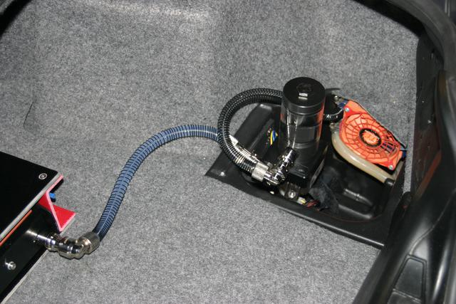
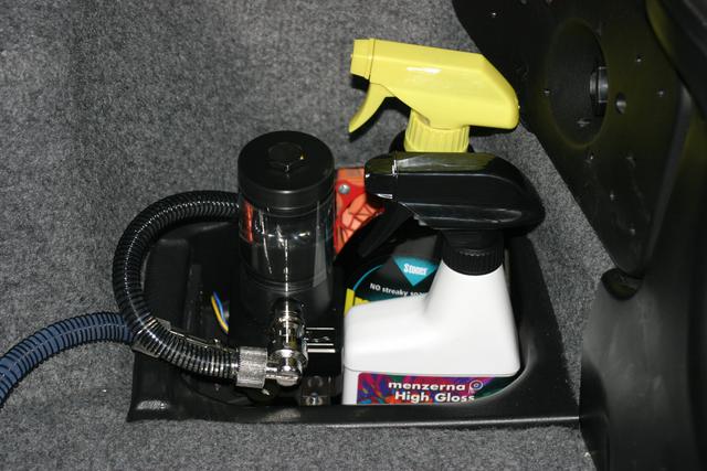
I also solved the resorvoir whirlpool problem. I dropped a piece of 1/16" thick perforated PVC in the resorvoir. I don't think it has any effect on flow rate, but it killed the whirlpool. Previously, I couldn't actually bleed the system via the resorvoir with the pump running; bubbles would just get sucked down into the pump and recirculated. When I first put the PVC in, the system had already been bled as much as possible without the PVC, and the resorvoir filled. After a 10 mile drive with the PVC in place, the resorvoir was half empty. It looks like it's because the PVC piece allows the bubbles to go to the top of the resorvoir. Either that or I have a leak I don't know about. I'll check it tomorrow. I topped off the resorvoir.
-
Audio
- June 16, 2008
-
Audio
The Swiftech MCP350, EK DDC X-RES 100 and UNDesigns Absolute Pump Bracket arrived from Performance-PCSThe Koolance low-profile swivel elbow only sort of works in the resorvoir port. What I really need here is another VL3-F10L. I installed the pump using the UNDesigns pump bracket, but I don't think I'll keep it. The problem is that it's not rigid enough, so going over bumps in the road is going to cause the pump to move up and down quite a bit. I can make a more solid mount using fiberglass angle that I already have on-hand.
I'm running the pump in test right now to check for leaks. So far, so good (5 minutes). One minor issue: the resorvoir has nothing to prevent turbulence, so it tends to swirl air into the pump unless it's completely full. Given the high flow rate of the MCP350 pump, this is probably not a big issue for cooling efficiency. However, it does concern me that the pump might not always be fully primed.I fabricated a pump mounting bracket from fiberglass angle and painted it flat black. It's much more rigid than the arm on the UNDesigns pump bracket.
-
Audio
- June 13, 2008
-
Audio
More quick-disconnects arrived from Koolance, for the tubing from the pump to the waterblock and the waterblock to the fitting in the driver side carpet panel. I installed them. I can now completely remove the tubing for the amp without tools, and the routing is a little better. They don't conflict with opening the carpet flap to get to the battery compartment and tool tray.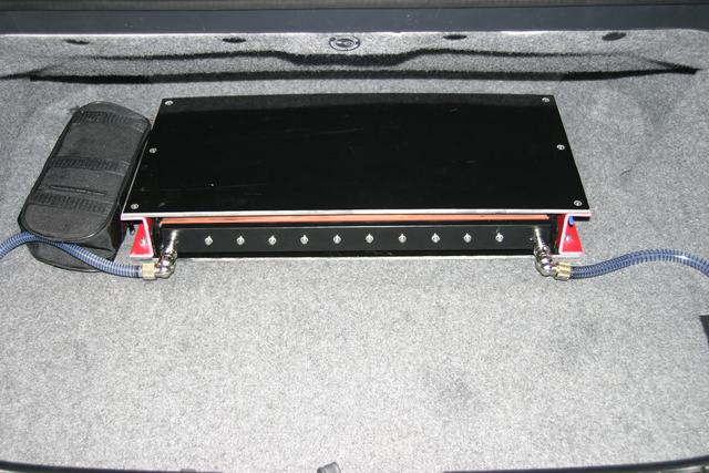
-
Audio
- June 11, 2008
-
Audio
The pump fittings are leaking. Try as I might, I can't get them to stop. A crack developed on the inlet port, presumably from bouncing around. Sigh, these parts aren't intended for an environment with a lot of vibration.I ordered a Swiftech MCP350 pump (Laing DDC 3.1), EK DDC X-RES 100 resorvoir and pump cap, and a UNDesigns Absolute Pump Bracket from Performance-PCS. Hopefully this will resolve the issue; the base of the X-RES 100 is delrin. The Koolance COV-PMP01P is aluminum and would work great, but there's no resorvoir. If necessary, I'll switch to using a separate EK Multioption RES 150 resorvoir and the Koolance COV-PMP01P. Other resorvoir options: Alphacool Cape Coolplex Pro 10, Alphacool Repack Mini Slot-In 3.5", Alphacool Mini Water Tank for Shuttle.
Note that to get more thread into the EK DDC X-RES 100 base, I could use McMaster-Carr 4860K654.
In the end, I think I'll wind up fabricating my own resorvoir out of aluminum and polycarbonate. I just don't have time to do it right now.
-
Audio
- June 10, 2008
-
Audio
The 50mm long M8 cap screws and the angled spacers arrived to bolt the amplifier to the trunk floor. With the new enclosure, it looks like I don't really need the spacers. I bolted the amp to the floor and it looks good. Whie I was at it, I put the final 2 screws in the top of the enclosure to hold the garolite to the C-channel.
-
Audio
- June 9, 2008
-
Audio
The BSPP tap and 11.8mm drill bit arrived to make the new waterblock cover. The 5mm allen wrench and snap-in clips to hold it also arrived. I drilled and tapped a piece of garolite to test the tap size. It appears to be correct.I also installed three snap-in clips for the allen wrench, inside the passenger side C-channel. They work fine for holding the 5mm allen wrench.
I cut the new waterblock cover to length, drilled the 12 mounting holes, then drilled and tapped it for the G 1/4 fittings. Due to the larger diameter of these fittings, I will have to notch out the fittings to install them since they'll be right against the last mounting screws. I tried just not installing those mounting screws, but I get a small leak on the driver side. I have G 1/4 to barb fittings to use until the new fittings arrive, I'll try notching those.
I powdercoated the waterblock cover in sable black. I didn't fuss over it since it gets hit by cargo; I just wanted something other than the bare aluminum.
I used Loctite 384 to adhere the copper waterblock to the amp, with 7387 activator. Previously I used Arctic Silver III, but it's expensive, has no adhesion, and is not fun to clean up. The Loctite 384 seems sufficient and was less messy to apply. It should also be less messy to remove when necessary, since it sets up harder.
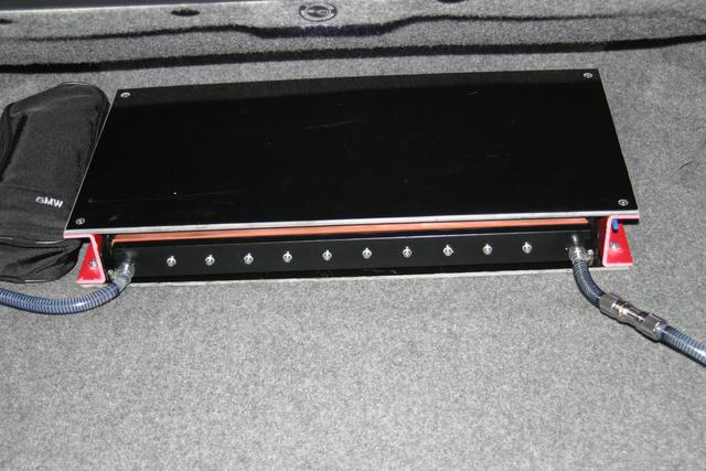
Taking a closer look at the fittings, I don't think I can notch them. I wish I hadn't drilled the two mounting holes closest to the fittings. I can always make another waterblock cover later, of course. For now, I've filled those two holes with silicone. I'll wait until tomorrow to check for leaks again, to give the silicone plenty of time to cure. The picture shows why I want quick-disconnect elbows on the amplifier waterblock.
-
Audio
- June 6, 2008
-
Audio
I started creating the new amplifier enclosure. I'm being much more picky about the measurements this time around, just so I get the bolt holes more exactly aligned for the rivet nuts in the trunk crossmember. I first created the two C-channel pieces, replicating what I had done for the first enclosure. I then attached them to the trunk floor and made them parallel. I then took measurements and cut the bottom panel, making sure it was square on each corner.I then carefully aligned the bottom panel to the C-channel pieces such that the holes in the C-channel were the correct distance apart, clamped them, and drilled mounting holes for M6 cap screws to hold the bottom panel to the C-channel pieces. I then installed the screws and locknuts and did a test fitment in the trunk. It's fine.
I then removed the whole thing and measured, cut, routed and drilled the top piece. I then installed the amp and fastened the top piece.
Putting it all back in the trunk, I realized I need longer M8 cap screws. The longest I have are 35mm. It looks like I can't get stainless steel ones longer than 40mm that are fully threaded. Not a big deal, I'll order 50mm partially threaded ones since I know I don't need fully threaded screws. The 35mm works on the driver side but I need longer ones for the passenger side. I can probably find a steel one at the local hardware store that will work in the interim, even if it's a hex head. I'm also ordering a pair of McMaster-Carr 95543A500, which are angled stainless steel spacers. They're 45 degrees, I'll have to grind them to the desired angle.
-
Audio
- June 5, 2008
-
Audio
New fittings arrived to shorten the amount of tubing on the right side of the trunk. I installed the new disconnect in the carpet on the driver side with the diamond plate. It doesn't look too bad, and it'll definitely work. I connected the tubing to the back of it. I also put hose clamps on the radiator on that side. I don't know why I didn't put any there in the first round, other than the fact that the barbs are very difficult to reach.I finished the remaining work to use the new cooling setup. While I was behind the driver side carpet, I put hose clamps on the radiator barbs. I don't know why I didn't do that before. The whole setup is pretty good now, but I ordered some more Koolance fittings to make it as nice as possible. Namely some G 1/4 to 3/8" male quick-disconnects for the waterblock connections, along with female quick disconnects to 3/8" compression to mate to them. Same setup for the pump output. This will let me completely remove the cross-trunk water lines before removing the amplifier, which lessens the chance of me dinging the bumper with a dangling quick-disconnect. It also eliminates the hose clamped barbed fittings at the amplifier waterblock, which will be a cleaner look and much less likely to scratch cargo. Since the female elbows swivel, it will also greatly reduce stress on the threads in the waterblock when there is cargo in the trunk. It will also angle the tubing parallel to the trunk carpet hinge.
I'm awaiting more garolite and fiberglass C-channel to make a final version of the amplifier enclosure. I'm going to flip the C-channel so the legs face outward, which will let me use simple socket head cap screws on just the lower edge of the C-channel to hold the amplifier. I can use angled spacers to accomodate the M8 screws. I will need something to hold the allen wrench so I always have it with me. If I wrap the allen key with heatshrink, McMaster-Carr 7586K11 will probably work.
-
Audio
- June 4, 2008
-
Audio
In preparation for the remaining fittings, I installed the Koolance VL3-M10B-P bulkhead quick-disconnect in the driver side carpet piece. I will be using a VL3-F10L female swiveling elbow quick-disconnect to mate to it. Since my previous disconnect was very large, I had to fabricate a mounting plate front and rear. I used diamond plate aluminum since it's what I had on hand. Later this will be replaced with 7075 aluminum I ordered from McMaster-Carr.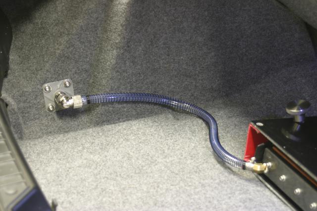
-
Audio
- May 30, 2008
-
Audio
I finished installing the new pump. With the existing fittings, I had to use more tubing than I'd like, in order to avoid kinks. I ordered some new fittings from Koolance to correct it, as well as some spring wrap for the tubing to help prevent kinks.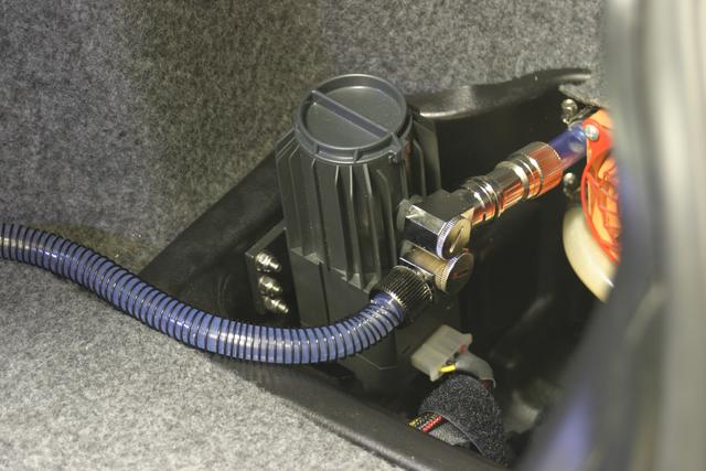
-
Audio
- May 28, 2008
-
Audio
The new fittings arrived for the new waterpump, along with some Koolance VL3 quick-disconnects and the Fezer tubing. The new fittings work fine on the pump but need hose clamps since they're single-barb. The Koolance quick-disconnects are very nice. I've figured out where to put the pump in the mobility kit bucket, and used Loctite 325 to bond a 1/16" piece of fiberglass to the mobility kit bucket for support. I may later lay up some fiberglass on more of it to add more support. I need to make a Molex extension cable for the pump, and of course cut and fit the tubing. I've already fit one of the Koolance disconnects to the input side of the amplifier waterblock.
-
Audio
- May 23, 2008
-
Audio
The new waterpump arrived. It's nice, but the fittings that were sent will not work. I ordered different ones from frozencpu.com. I also ordered some new tubing (Fezer 3/8" ID) and some Koolance VL3 quick-disconnects. I think my slow water leak has been from one of the quick-disconnects being stressed at an angle. That will be resolved by the new pump, but the Koolance quick-disconnects look like they're nicer than the ones I have now.
-
Audio
- May 13, 2008
-
Audio
Note to self: check out www.frozencpu.com for some new Koolance quick-disconnects and other watercooling parts.
-
Audio
- May 12, 2008
-
Audio
I installed a pair of M8 rivet nuts in the top plate of Randy's reinforcement work so I can bolt down the amplifier. I have stainless steel knobs on M8 rods to bolt it down. However, I don't really like it at the moment since the amplifier isn't level with the plate... the knobs are visibly angled so it looks sort of half-ass. I haven't decided what to do about it yet. If I make the amplifier level, I lose some cargo space. I might just flip the C-channel and use cap screws that would be mostly hidden. On the upside, the amplifier now doesn't move at all, nor does the trunk carpet.
-
Audio
- April 1, 2008
-
Audio
Wiring is done to make the amplifier easy to unplug and remove. Note that the 3-pole connector is just to tee to the ITPS power supply that runs my water pump and the Digital Doc 5 fan controller.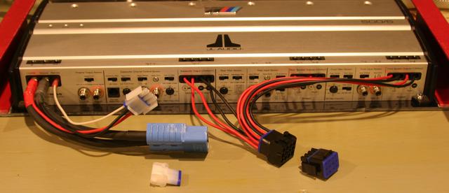
-
Audio
- March 17, 2008
-
Audio
I have new Anderson SB contacts now, so I can make new amplifier power cables if desired. I also noticed that Digi-Key carries the AMP Universal MATE-N-LOK connectors in black and red. Mouser carries the gold plated contacts, which are better than the tin plated ones I ordered from Waytek; I ordered enough for the amplifier speaker connector.
-
Audio
- March 7, 2008
-
Audio
I finished the first pass at fitment of the revised amplifier enclosure. This is just my old one, tweaked a bit. Electrical grade fiberglass sides, G-10 top and bottom. The objective here was to be able to later bolt down the amplifier and enclosure, and remove it all as one piece with easy disconnection. I used Anderson SB120 connectors for the power. Right now I have banana jacks for the speaker wires, but that's going to change to a single AMP Universal MATE-N-LOK. I also have simple tab disconnects for the pump control wiring, but that's going to change to AMP Universal MATE-N-LOK too.
-
Audio
- October 9, 2007
-
Audio
I finally opened the package from installer-parts.com. Umm, the PMHPFD4 didn't come with the contacts! So it's useless. Nice parts, but I can't use them.I ordered a y-cable from installer.com so I can run two hidden amplified antennnas. It may work, or it may suck. From playing around tonight, the hidden antenna doesn't work all that well in any location where I can reasonably position it. But then my stock antenna doesn't work all that well either. If I'm going to have Gary do some work on the fender, I should consider moving the antenna to a position where I could use a power antenna, say a Metra PW6. The last time I looked at this, it didn't look easy due to the way the fender is constructed. However, I suspect I can make it work if the fender is off the car. P/N for the rear left fender is 41.35.0.307.014, list price is $277.50. The difficulty here isn't the fender, it's the body skeleton. Look at Randy's pictures if he has any.
-
Audio
- September 16, 2007
-
Audio
I ordered some Andersen PowerMod HP connectors from installer-parts.com (River Oaks Car Stereo). A dual-pole 4-gauge male panel mount (PMHPMP4) and a dual-pole female connector (PMHPFD4). I also ordered a hidden antenna to try, since none of the Metra powered antennas will fit under the fender in the stock location (the wheel well is in the way).I think I'm going to need to buy a Scosche T-1 crimper to crimp the connectors. cardomain.com has it for $180. It looks like it has hex dies, which is what I want.
-
Audio
- April 3, 2007
-
Audio
I ordered the new Alpine iDA-X001 from Crutchfield. Yay! UPS tracking number 1Z2807700328704579. I've been saving up for this ever since it was announced. No CD transport, hence fewer moving parts to fail. I never really use the CD in the car anyway, I only use the iPod. I will now save up for a 5th-generation iPod, 80G black. In the interim, I'll use my older iPod with the high-speed cable.I still want a way to mute the stereo when my GPS is talking to me. If I pull the mute input on the head unit to ground, I think it will mute the music. OR do I need to pull it high (5V? 12V?)? Maybe I just need a current-sensing device wired into the speaker of the GPS? Something like the PIE ALP/Ai-AUX?
-
Audio
- March 18, 2007
-
Audio
I started making a makeshift amplifier cover. I used a roundoff bit in the router to soften 3 of the edges of the black fiberglass sheet. I then cut 2 pieces of the angle fiberglass, and bolted them to the black fiberglass sheet with stainless steel M4 countersunk allen bolts and nylon-insert locknuts. This is mainly for test fitment in the trunk. It looks like I should take some height off the angle pieces to bring things closer to the amplifier. I should also take some depth out of the sheet; maybe 2" or so.I'd like to cover the top with raised-disc antislip rubber. McMaster-Carr P/N 6292T271. I can adhere it with 3M #80 adhesive, McMaster-Carr P/N 7610A16.
-
Audio
- February 11, 2007
-
Audio
I ordered some 90-degree angle fiberglass for the amplifier cover. I would like to clean up the connection stuff, so it's easy to get the amp in and out of the car. The RCA connections are not a big deal, but power and speaker runs suck. I can use the banana plugs for the speakers. What about power? If I want to get fancy with the RCAs, I can use Switchcraft RCA pass-throughs (EHRCA2BXPKG at Mouser).I need a better power distribution setup. The PITA issue at the moment is the pyro stuff in the stock positive battery cable, which makes mods awakward. Hmm, can I fit the terminal block I made for the Optima in the battery box with the Interstate? Note I only need 4 gauge power to the amplifier. Can I use a StreetWires BT2N on the battery? How about just using Streetwires DB0240's?
-
Audio
- February 25, 2006
-
Audio
I applied deadening material to the inside and outside of the z3bass enclosure, and put some pilyfill in the enclosure. I re-installed in the car, and secured the driver with all of the screws.It sounds quite good. It needs a road test, of course. I queued some Pink Floyd, namely "The Happiest Days of Our Lives" and "Another Brick in the Wall" from The Wall. Not bad. I've still got a little but of noise (and possibly some huff), but this is easily the best sounding setup I've had in the car. It will be awesome with the top up or the hardtop on.
It needs a road test. Dave Matthews would be good, as well as some Ben Harper. I can just take the Stand Up CD with the Blind Boys of Alabama CD with me. "Wicked Man" on the Ben Harper CD is one of my new favorites.
-
Audio
- February 22, 2006
-
Audio
I ordered some sound deadening material from http://edesignaudio.com. I also ordered polyfill, banana plugs, etc. from http://www.partsexpress.com.
-
Audio
- February 5, 2006
-
Audio
I picked up some fender washers, neoprene fender washers and M8 bolts from the hardware store. I will cut the heads from the M8 bolts and grind them to a point so they can be used to mark the bottom of the enclosure for drilling. A fender washer will be used to squeeze the enclosure plastic between a pair of the neoprene washers.It's worth noting that at the present time, I'm concerned about rattling against the rest of the rear console, since the enclosure won't be fastened to it at all. I need to do some out-of-the-box thinking to see if I can come up with a way to attach it without doing a bunch of composite work.
-
Audio
- February 4, 2006
-
Audio
I installed a pair of knurled M8 nutserts in the sheet metal underneath the subwoofer enclosure. These will be used to bolt in the new 8" z3bass.com subwoofer enclosure. The two holes were already there, but were only about .375" in diameter. I drilled them to 1/2", then slowly enlarged them with the Dremel and an acorn-shaped stone until they were big enough to take the nutserts. I only made them large enough to where I could tap the nutserts in with a hammer. You want as snug as fit as possible with these things. I used the Marson 325-RN nutsert tool to secure them. Nice tool, works great.
-
Audio
- June 26, 2005
-
Audio
The amplifier watercooling block was leaking very slowly between the copper and polycarbonate. I took it apart and installed a silicone gasket cut from a 1/16" sheet. No more leaks.
-
Audio
- January 10, 2005
-
Audio
I ordered some small parts from Bell BMW to finish putting the trunk back together. Blind plugs, new positive battery cable cover, new trunk lamp, etc. My trunk lamp had the bulb mounting plastic melted by the bulb. No idea what BMW was thinking putting a 10W bulb in there, if you leave the trunk open for a while it gets too hot. I have an LED festoon to put in when the new trunk lamp arrives, so it won't happen again. It's much like the one I'm using in the cabin overhead.
-
Audio
- January 9, 2005
-
Audio
I decided to put some holes in the carpet that covers the ragtop compartment, to pass amp wiring. It's moot in the long run, since I intend to cover the amplifier and the cover will hide the holes as well as the wiring. I bought some fiberglass to do this a long time ago, I just haven't gotten around to making the cover.
-
Audio
- January 3, 2005
-
Audio
Today was a holiday from work, so I got some more work done. I added braided sleeve to the subwoofer speaker run (from amp to the stock wiring). I added braided sleeve to the run from the left crossover outputs to the speaker wires in the car harness. I made a braided sleeve cable for the runs from the amplifier rear speaker otuputs to the speaker wires in the car harness. I tidied up the left crossover wires and subwoofer wires on the left side of the trunk. I also fastened the cables that cross the trunk under the ragtop compartment.I still need to decided what to do about wiring to the amp. I'd sort of like to do it under the carpet, and suspend the amp over the dip in the trunk. That'd alleviate the carpet contortion issue.
-
Audio
- January 1, 2005
-
Audio
I removed some old audio wiring from the trunk. Some of it was not being used (from way back when I tried to use the wiring in the car harness for the head unit to amp runs). The rest were things I wanted to rewire to proper length for the JL Audio 500/5.I made new cables for the left front and right front outputs from the amp, which run to the crossovers. I used Monster XP speaker wire, with spade terminals on the crossover ends and the crimp-on barrels I got from Parts Express for the amp end. I labelled everything on the amp end, and labelled +/- on the crossover end using silicone splicing tape. I also put braided sleeve around both sets.
I cut the positive and negative power cables to length for the amp. for the positive one, I his the fuse in the corner on the right side of the trunk. The fuse assembly was nabbed from my old StreetWires amp wiring kit; it uses an allen set screw to clamp to the 4-gauge welding cable.
I tested the left front and right front channels; all is well.
-
Audio
- December 29, 2004
-
Audio
The CDA-9835 head unit is installed in the car as of last weekend. I like it, and the illumination nearly perfectly matches the BMW amber. I also like the fact that I can turn off the internal amp via the SETUP menu. I've also played with iPersonalize a little bit, and I'd sure like to hack the file format so I don't have to use their Flash-driven Web stuff. It works OK in Safari on my laptop, it's just not very convenient.The KCA-420i works well. My only complaint is the slow scrolling on the head unit. I assume this was done to prevent a CD changer from going bonkers trying to keep up, but it's not appropriate for the KCA-420i and an iPod.
Today I received the remaining parts to make my own amplifier power wiring setup. 4-gauge welding cable (very flexible and not bling-bling), 8' of red and 8' of black (from McMaster-Carr). Some Rockford-Fosgate RP6220 4-gauge right-angle ring terminals to use on the battery side (nice because they're reusable, unlike crimp-on rings). I also received some 4-gauge crimp-on ring terminals from Parts Express, but will not be using them now that I know I can fit the RP6220's on the battery. I also received some funky crimp-on sleeves to put on the ends of my speaker wires so I'm not just clamping down on raw copper wire.
The plan for the KCA-420i is to install it on a custom-made Kevlar knee bolster that will replace the original driver's-side knee bolster I removed earlier this year. I'm also thinking about fabricating a dock for the iPod (probably carbon fiber) so I don't have a loose cable in the car. For now I'll put the iPod in my driver's-side cargo net. The only tricky part about a dock: the iPod dock connector is latching, you have to squeeze the sides of the connector to remove it.
-
Audio
- December 18, 2004
-
Audio
At some point in the fall, my CDA-7878 head unit's CD transport mechanism self-destructed. I took apart the head unit, to find bent parts. I also found that none of the motors were working; the disc didn't spin up, and the eject motor didn't activate. I had to manually manipulate things to get the CD out. I then found that the CD insertion motor didn't activate either. So none of the motors were working.Time to replace the head unit. I ordered an Alpine CDA-9835, and also ordered an Alpine KCA-420i iPod interface. This is the best iPod setup I've seen, since I have control from the head unit as well as ID3v2 tag display. QuickSearch works, shuffle works for playlists and the whole iPod, etc. I can put the 40G iPod wherever I want, since it doesn't need to be in view. Of course I can't leave it in the car, since I live in Michigan. :-) It won't handle the temperature extremes.
-
Audio
- August 17, 2004
-
Audio
3/16" Garolite G-10 sheet arrived, so I can make a prettier cover for the jack tray to hold the Digital Doc 5. All of the quick-disconnect fittings arrived too. Darn, they're all HUGE. They'll do for now, but I think I'll wind up with the Jiffy-Tite ones in the long run. However, I really like the polyproylene panel-mount one, it's a good color combination for my trunk (light and dark gray), and it's lightweight and won't scratch anything.I also received the adapter bushings and plugs to use in the top of the resorvoir for fill and bleed. I've already drilled and tapped the resorvoir and installed them. I also installed one of the huge steel quick-disconnects. I replaced the straight fittings in the waterblock with 45 degree fittings. I also made the hole in the left side carpet for the panel-mount quick disconnect.
-
Audio
- August 14, 2004
-
Audio
I ordered some black G-10 garolite from McMaster-Carr to replace the PVC holding the Digital Doc 5 in the jack tray. I also ordered some more VHB tape.I filled the system with distilled water. Everything looks good at the moment. Water flow is good, and a good quantity of air is coming out the trunk vents with the trunk lid closed. I can't hear the fans over the exhaust, but they are indeed loud when I turn the ignition off.
I routed the water line that crosses the trunk (from the left to right radiator) behind the trunk trim panel. Plenty of room in there by the harness. So that's hidden and can't conflict with the carper flap.
I put worm-drive hose clamps on the radiator connections on the right side of the trunk. I put the carpet that covers the ragtop compartment back in place. I'm waiting for quick-disconnects (including a panel-mount one for the carpet on the left side) to wrap up the water work. I'll flush the system thoroughly when they arrive. I also need to install fill/bleed fittings in the top of the resorvoir. I ordered some aluminum bushings (3/8" NPT male to 1/4" NPT female) for this purpose, as well as some nickel-plated brass hex key plugs to plug them when not in use. I also ordered some 1/4" NPT male to 3/8" hose barb swivel fittings to use when filling the system.
-
Audio
- August 13, 2004
-
Audio
I installed the Vantec Tornado in place of the Panaflo on the left trunk vent. With the trunk lid closed, I checked the airflow. It's quite impressive! Of course it's loud, but I won't have this fan turn on unless things get warm. It shouldn't be louder than road noise, but that remains to be seen.I also ran the wires for the left trunk vent fan and put them in some flame-retardant braided sleeve. This connection can be disconnected at either end, I used standard 3-pin fan connectors. Other than doing some wiring cleanup and braided sleeve for the power to the ITPS, I'm ready to put some water in the system and do some real-world testing.
-
Audio
- August 10, 2004
-
Audio
I ordered some parts from McMaster-Carr. Locknets for the resorvoir fittings, a few elbow fittings, etc. I also ordered a new 3/8"-18 NPT tap.I put a 3/8 NPT fitting in the top of the resorvoir. It turns out that the resorvoir wall is thick enough to get a good three threads, so the polypropylene fitting fits nicely and feels solid.
I cut a piece of perforated PVC sheet (3/16" thick) to cover the empty tool tray on the right and hold the voltage regulator gear and Digital Doc 5. This is not what I want to use in the long run, but it'll work as a temporary solution. In the long run I'd really like a piece of aluminum or fiberglass. A 12"x24" piece of 3/16" black G-10 is $32.55 from McMaster-Carr. I have some copper-clad FR-4 around somewhere, which could be powdercoated.
I need to wire power to test some things. All three input for the ITPS can come from the amp lead lines, since I need the turn-on wire in addition to hot and ground. Molex connectors would be fine on the ITPS side. The output of the ITPS needs to go to the pump and the Digital Doc 5. Molex would be fine there too.
The Fan 1 output of the Digital Doc 5 should go to the Thermaltake fan in the passenger side trunk vent. The Fan 2 output should go to the fan on the driver side trunk vent.
I haven't yet decided where to put any of the thermal probes for the Digital Doc 5.
-
Audio
- August 9, 2004
-
Audio
I poured the Devcon 80 urethane in the gap in the Mobility Kit case (between the pump compartment and resorvoir). Very easy to do, can be poured in a thin stream to avoid mess or trapped air.Some dripped down into the pump compartment before setting up, which I expected. I let it set up a little (i.e. stop dripping), then cleaned it up with Goof-Off (which worked very well).
Several hours later, the Devcon had cured enough to handle. I removed the tape and the nipple. All is well.
-
Audio
- August 5, 2004
-
Audio
Well, the butyl caulk was a bad idea, it did not cure at all in the center. I should've known better. I got most of it out today, but it was a messy job. I will use pourable urethane instead, and Randy has graciously offered me the remains of his Devcon 80. I'll pick it up tomorrow.I JB-Welded the nut to the nipple for the resorvoir-to-pump connection, in hopes it'll stay on. This will make removing/installing the pump easier.
I drilled a 5/8" hole in the side of the pump compartment for output. Right now I'm just using a 1/2" NPT female to male elbow and then a barbed fitting.
I need to pick resorvoir fittings. I need one for input from the radiator, and a pair for fill/bleed in the long run. I really can't use bulkhead fittings in the size I need, unfortunately. The holes would need to be too big which would make matching the curvature difficult and prone to leaking. At the moment I'm thinking I should just JB Weld some fittings into the resorvoir. 3/8" male NPT to 3/8" barbed would work nicely. Note that a 3/8" NPT fitting's thread is 3/8-18.
-
Audio
- August 3, 2004
-
Audio
I filled the gap between the pump compartment and resorvoir with butyl caulk. When fully cured, this should help prevent the side of the pump compartment from flexing too much, and further seal up the resorvoir. It should be cured on the surface tomorrow, but will take a week to fully cure. This was a messy job, it would've been easier to use casting urethane (mixed thin). But I don't have time to wait for casting urethane to be shipped.
-
Audio
- August 2, 2004
-
Audio
I took a quick measurement today of the volume of the tire goop canister that I'll be using as a resorvoir. It's about 900ml.The second layer of JB Weld is curing on the polycarbonate window in the canister lid.
I made the hole that passes through the side of the resorvoir for input to the pump. I didn't want to try using a 90-degree die grinder or drill to get in there, it seemed too risky. So I drilled a 1" hole in the bottom of the pump compartment so I could drill a straight hole into the resorvoir. I then put the 1/2" female NPT to 3/8" male NPT reducer on the pump and put the pump in the pump compartment. I fed a 3/8" short nipple through from the resorvoir and screwed it into the adpater on the pump inlet. I then put a larg, thuck rubber washer on the nipple in the resorvoir, then an O-ring, then a custom cut piece of thin Delrin, then a long nut (intended for compression fitting, but it's what I had on-hand that fit).
I filled the resorvoir with water and am waiting to see if it leaks. I don't really have a good feeling about it right now, the side of the pump comartment flexs quite a bit when things are snugged up, even though I added some Delrin reinforcement. It looks like I'll need to sandwich something between the wall of the resorvoir and the wall of the pump compartment. It might not be a bad idea to just fill that whole area with pourable urethane or even silicone caulk?
-
Audio
- August 1, 2004
-
Audio
Well, last night I had an inspiration: use the Mobility Kit case as the water resorvoir and pump housing. The tire goop canister is perfect as a water resorvoir, and is positioned at the top, where it should be (to trap air bubbles and prevent them from being recirculated).So, I gutted the Mobility Kit case and cut a hole in the canister lid, and JB Welded a polycarbonate window in. This will let me see the water level without opening the canister, as well as observe water flow if I put enough slack in the hoses to lift the Mobility Kit case out of the bucket while still connected. I will do a second layer of JB Weld once the first is cured.
I need to pick some quick-disconnect fittings. I was looking at the Jiffy-Tite, and Randy says I should look at Parker or Swage-lock too.
-
Audio
- July 31, 2004
-
Audio
I bought some more tubing today to rig up the watercooling in the trunk for some testing. This is not what I want in the long run, but I need something that works for testing. I bought clear vinyl tubing; 10 feet of 3/8" ID (9/16" OD) and 10 feet of 5/16" ID (1/2" OD). I'm using the 3/8" ID almost everywhere, except where I can't (water resorvoir). All of the tubing is connected now for testing.I started mocking up the layout for the voltage regulator board, the Digital Doc 5, and the water resorvoir. I cut holes for the resorvoir and the Digital Doc 5 in a piece of hardwood plywood. I test mounted them, and things look good in terms of location. The Digital Doc 5 is on the bottom, the voltage regulator board in the middle, and the resorvoir on top. They're all centered.
Hence I think I can run with this layout, and I just need to figure out what I want the rest of the box to look like.
-
Audio
- July 30, 2004
-
Audio
The M is back on the ground and driveable. I wrapped up the first round of suspension work, having officially installed my new ragtop protector cap setup in the ragtop compartment (lets me access the rebound adjuster on the KWs, but protects the ragtop from being poked).While I was in the ragtop compartment and had the liner out, I put the grommet back in correctly on the driver's side. Part of it had come out of the sheetmetal. Now it's all spiffy, including the MicroXLN 6-channel cable. That cable runs right next the subwoofer wires now, instead of under/around the roll hoop area. there was more room, and it'll be easier to maintain.
-
Audio
- July 26, 2004
-
Audio
Our new Audi TT 3.2 will arrive tomorrow. So I'm trying to get the M back on the ground. I just finished the first round of cleaning on the passenger's side wheel well liner. Like the other side, there was a lot of road tar stuck to it from last year's trip to Canada. So the first round included tar remover to get that off, then mineral spirits to remove the road dust that likes to seep into the polypropylene. I'm waiting for it to dry before I go at it again.
-
Audio
- July 25, 2004
-
Audio
I picked up a 2.375" hole saw. It may or may not work on the Delrin piece I have, but I know it'll work on plywood. :-)I also picked up some 2" #8 sheet metal screws to cut down for use on the Vantec Tornado fan, more blue Loc-Tite, some M4 screws to mount the resorvoir (not sure if they're right, I just guessed), some Gogo hand cleaner, and more JB Weld.
-
Audio
- July 24, 2004
-
Audio
I installed the radiator and fan on the passenger's side trunk vent. To do this, I cut a couple of slits in the carpet for stress relief, and I had to take a big chunk out of the mobility kit bucket to be able to reinstall it. I am using the Thermaltake fan on this side. I may or may not run it at full speed, depending on how loud it is. I'd like to run it at full speed, it will only come on when things get warm and the amp is on, but we'll see how it sounds.If I want to do the fancier mounting method for the resorvoir, I need a 2.375" hole saw, or I need Randy to bore the hole for me. It's not like I don't need a 2.375" hole saw (would be handy for 60mm fans).
-
Audio
- July 12, 2004
-
Audio
The Vantec Tornado and Thermaltake A1357 arrived from Directron. I will try them on a radiator attached to a trunk vent, to compare noise and air flow to the Panaflo M1A.
-
Audio
- July 10, 2004
-
Audio
I need to put the center console and rear console back together. I am close to having the center console back in. All the buttons are reconnected, as well as the cigar lighter. The cigar lighter is a pain in the butt due to the shortness of the leads and the socket bulb having a tendency to just fall out when moving the console. In fact, from the factory my bulb was out of the socket and it surprised me how bright the lighter ring was when the bulb was installed correctly the first time I had the center console out.The gauges are back in the center console, as is the OBD-II port. Now I just need to put the door chime on and carefully put the center console all the way into position (so as to not knock the door chime off). I'm taking a break at the moment to let my hands rest from the prolonged contortions needed to install the gauges. :-)
I am having trouble getting the center console back in place, something is preventing it from going up to the dash vents. Just the last 1/2" or so. I did test to see that everything is still working, including the new MicroXLN cable (I put the subwoofer back in temporarily). Seems good, now if I can just get the center console to go in without taking it all out again...
Ah, it seems the guide pins weren't quite going in the holes. Duh, I forgot about those (near the vents in the dash). The center console is back in, and the rest of the interior is back together. All is well.
-
Audio
- July 9, 2004
-
Audio
The MicroXLN 6C-5M cable arrived. I've started installing it. I pulled the ragtop liner out to make access to the grommet easier, and loosened the rear console. Obviously I removed the driver's side roll hoop. The old cable was harder to remove than I remember it being to install. It had also been squeezed pretty hard somewhere, exactly where I'm not sure; I just saw the pinch in the cable after I had pulled it out of the rear console area. I suspect it was pinched by the Sunfire subwoofer enclosure. The new cable is through the grommet in the trunk, but I'm going to route it a little differently than the old cable from there forward so it doesn't get pinched. It'll get routed next to the subwoofer cable.I removed the center console to remove my old MicroXLN cable. This was a lot of work with all the things I've done under the center console. The old cable is out now, and the new one is routed under the center console. I need to route it through the rear console again, I screwed up and left a loop outside of the rear console. Sigh, I really hate working with the center console, it's a real headache.
I should not put the ragtop compartment liner all the way back until I've installed the Rogue rear shock mounts.
-
Audio
- July 8, 2004
-
Audio
I finished the initial installation of the z3bass.com enclosure. I have not installed the included rubber spacers (optional). As it is, the enclosure already makes the trim look bad because it pushes it out (not just the back, but side-to-side). For the price, I can't really complain, but the fitment isn't great and it wouldn't have been impossible to make the enclosure a few millimeters smaller in critical fit dimensions. At any rate, I'll be thrilled to have an 8" custom composite enclosure fit-wise, since I've never liked the way the rear console goes together.The upside of the z3bass.com enclosure is that it sounds very respectable for a 6w0 within the contraints of the stock location. It also doesn't have the problem the Sunfire had with the driver smacking the rear panel and destroying its dust cap. Surprisingly, I've also got no rattling at all. It's not as tight as I'd like (I prefer sealed enclosures), especially at higher volumes, but it's definitely the best bang for the buck I've seen. The JL drivers are very nice, which I already knew, but Kevin did a nice job on getting this kind of sound out of what is a very small internal box volume.
-
Audio
- July 7, 2004
-
Audio
The MicroXLN 6C-5M cable shipped. UPS tracking number 1Z7285770322865503.The perforated PVC arrived for the trunk capret mods. The copper M4 washers arrived to dress up the waterblock mounting screws. I also received a 1/2" NPT elbow and Y-adapter to connect the pump to the water resorvoir.
I picked up the 6w0 driver from Mr. Tunes III. I mounted it in the z3bass.com enclosure. I really hate that the z3bass.com enclosure doesn't attach to anything, it's really lousy on that front. But it's all temporary anyway; the Mr. Tunes III fiberglass guy said he could do the 8" driver enclosure I'd like to have done. I gave him a quick tour of what I'd like done. He could cover it in leather, but I'm thinking I want it painted since leather is harder to take care of over the long haul. It'll cost more to have it painted since the finish work is more difficult, but I think it'd look nice in body color.
I cut some of the ridge from the rear of the console to make room for the JL Audio driver in the z3bass.com enclosure. Note to self: I'm using the blue/red wire for subwoofer positive and the blue/brown wire for subwoofer negative. The enclosure fits snugly in the rear console. I suspect it's going to rattle everything back there, it's touching too many things.
I will wind up snipping off the stock connector for the subwoofer, since it's just something that can rattle and when mated, there really isn't room for it with the z3bass.com enclosure. I should probably pair up the wires to support more current; blue/brown with brown, blue/red with yellow.
-
Audio
- July 6, 2004
-
Audio
The perforated PVC shipped from McMaster-Carr. The 8mm compression fittings shipped from highspeedpc.com. The Vantec Tornado and Thermaltake A1357 shipped from Directron (UPS tracking number 1Z13643W0360623245).The JL Audio 6w0 arrived at Mr Tunes III, but I didn't have time to pick it up.
-
Audio
- July 5, 2004
-
Audio
I ordered a new Monster MicroXLN 6-channel cable, 5M length. This is to replace the 6M length one that leaves a bundle of slack in the trunk (the black cable you might have noticed in my picture of the left trunk vent with the radiator and fan installed). I considered the 4M length, but I think that'd be too short when I want to move the amp around w/o disconnecting all of it.I still haven't heard from Mr. Tunes III about my 6w0 driver. I'm assuming I'll get a call tomorrow.
I placed the order for a Y-connector and 45-degree 1/2" pipe gender changer to connect the resorvoir to the pump. The Y-connector has a pair of instant fittings for 3/8" OD tubing that will connect to both of the bottom ports on the resorvoir. It has a single male 1/2" NPT output that will go in to the 45-degree elbow. The 45-degree elbow will be connected to the pump inlet. I got these parts from McMaster-Carr. The Y-connector is P/N 51235K196, and the elbow is 9162K124. I also ordered copper M4 washers, P/N 98044A216.
I also placed an order for the additional fittings I need for the water resorvoir. 8mm compression fittings from highspeedpc.com.
Finally, I ordered gray perforated PVC to replace part of the carpet under the ragtop compartment, to permit air to enter the trunk more easily from the cabin. It's 1/16" thick, with 1/8" holes on 3/16" centers (staggered pattern). Open area is 40%.
-
Audio
- July 4, 2004
-
Audio
I ordered an 80mm Vantec Tornado (TD8038H) fan in case I need higher CFM for the radiator. The Vantec Tornado is rated at 84 CFM at peak rpm. It's also 38mm deep, which should help in dealing with static pressure. I also ordered a Thermaltake A1357 80mm fan, which is 25mm deep like most 80mm fans, but has a 75 CFM rating. It also comes with a speed control and thermal control. I suspect I'll use the manual speed control.
-
Audio
- July 3, 2004
-
Audio
I tested the Vantec Tornado and Thermaltake A1357 fans. The Tornado pushes a tremendous amount of air for an 80mm axial fan, and seems to do well with static pressure. However, it's very loud and has no speed control. If I use this fan, I'll want a speed controller and/or to only activate this fan by temperature threshold (from the Digital Doc 5). The Thermaltake doesn't push as much air and is weaker on the static pressure front, as expected (it's shallower). But it's less noisy, and came with an optional plug-on speed controller (varistor). This might be the fan I run all of the time on the passenger's side, which will help keep the pump from getting too hot.
-
Audio
- July 2, 2004
-
Audio
I started running the pump. I had to make a bleed/fill line to get air out of the system (using a tee), and it was more difficult to fill and bleed than most of my PC watercooling projects. I may need the valved quick-disconnects sooner rather than later, to make it easier to fill/bleed once it's in the car.No leaks at all from the waterblock. I need to put some Teflon tape on the 1/2 NPT fittings on the pump though, they're leaking slightly.
I checked out the vent on the driver's side of the trunk again, from the inside. Radiator with fan fits fine in the available space. I might even be able to fit a 38mm deep fan, which would let me push more air. Say a Vantec Tornado. Of course they're loud at full RPM, but I could use a speed controller to adjust.
To use the vent on the passenger side, I will need to cut some of the carpet and the bucket that normally holds the mobility kit. This is OK, since I was going to box off that area to hold the pump and resorvoir anyway.
I removed the driver's side rear wheel well liner to get at the trunk vent on that side. The P/N for the vent is 64.22.8.390.234. From the ETK, it looks like it's the same part on both sides of the car. Bell BMW wants $4.70 each for new ones. I took some pictures of the vent, with the radiator/fan assembly next to it.
I also looked up the part number for the bucket that holds the M Mobility Kit. That's P/N 51.47.7.894.322. Bell BMW doesn't show it in their system, but rust.mine.nu says $35.
I modified the driver's side vent to permit the radiator to sit closer to the vent opening. There are 2 water trays in the vent, one for each EPDM flap. I trimmed some of the depth off of them. I could have trimmed them flat, but it would not have done much good because there are tabs for the EPDM flaps on the back. So I cut roughly to the height of those tabs, and gave the radiator a very slight downward aim out the vent hole.
It's worth noting that if I turn the radiator on its side, I can trim more of the water trays away, and lay the radiator flush against the vent. In this orientation, it doesn't touch the tabs for the EPDM flaps. However, at the moment I'm reluctant to do this, because I don't wnat a local high spot inside the radiator that I can't see. Air trapped in the radiator will reduce cooling efficiency. With both of the barbs on the top, air can easily escape the radiator. The idea is for all air bubbles to wind up in the resorvoir, which can be topped off as needed if we lose water. Usually there's a tiny bit of evaporative loss in such a system, usually via the resorvoir lid. I might not lose any water here, since the resorvoir has allen-head plugs instead of a cap for filling. But of course I'll lose a tiny bit whenever I detach the quick-disconnects.<\p>
I don't know if the tabs that hold the vent to the body will support the weight of the radiator/fan assembly. If not, I'll need something like a reinforcement ring, maybe made of Teflon since it likely gets warm there from exhaust heat when the car is stopped and the exhaust is at temperature. I'd also like to seal the radiator to the edges of the vent... composite would be nice, and might eliminate the need to fasten the radiator to the vent by other means. Of course, at the moment, zip ties in the mounting holes of the radiator seem like a fine idea to secure the radiator to the vent.
-
Audio
- July 1, 2004
-
Audio
I assembled the waterblock and bolted it to the amp. I used Permatex clear flowable silicone to gasket the copper to the polycarbonate. I used Arctic Silver III thermal compound between the waterblock and the amp. I may decided to use a different compound later, since Arctic Silver is intended for surfaces that are very closely mated, and I don't really know how flatly the waterblock is sitting on the amp.I then put some water in the system, with only the waterblock, pump and resorvoir in the loop.
-
Audio
- June 30, 2004
-
Audio
I called Phil at Mr. Tunes III to ask about my JL 6w0 subwoofer. He said it should have arrived already. He's calling his JL rep. and asking for a tracking number. He'll call me back when he has the information.Phil returned my call, and he thinks the speaker will be here by Friday. He will call me when it arrives.
I also asked him if they do custom composite work, which would relieve Dan and I from doing the rear console work for the 8" Polk/MOMO driver. Phil said, "yes". I'll talk to him about it when I pick up the 6w0.
I went to Randy's so he could round the other edge of the waterblock for fitment. It turns out I may not have needed it, something else was in the way. However, it was a good idea regardless, since it gave me a little bit of wiggle room for the waterblock for screwhole alignment.
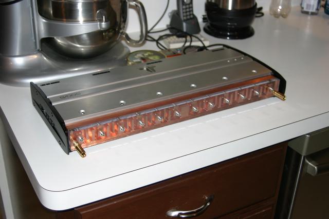
I test fit the waterblock to the amp, with the polycarbonate and the 40mm long M4 cap screws. Looks perfect other than the too-long barbed fittings I'm using at the moment.
-
Audio
- June 29, 2004
-
Audio
I drilled and tapped the holes for the fittings in the polycarbonate. I'm using 1/8 NPT fittings, so the drill bit was 21/64". I installed 1/8 NPT to 3/8" barbed fittings for now, but I don't expect to keep them; the long-term plan is to replace these with Jiffy-tite 22802 (Plug with 1/8" NPT Male Adapter), to which I'll connect Jiffy-tite sockets (probably 21406?).
-
Audio
- June 28, 2004
-
Audio
I cleaned up the burrs on the waterblock with the Dremel tool. I didn't work too hard on this, in part because I didn't want to spend a lot of time cleaning up copper dust. I also ran some water through the block just to see what it looks like. Looks good, and I think this is going to work very well thanks to the number of passes.I also cut, drilled and sanded the polycarbonate cover for the waterblock. I botched the first one at the very end (while making a countersink for the very last hole). On the second one, I decided to not countersink the cap screws. I may do this later, but the end ones shouldn't be countersunk since they're close to the fitting locations.
-
Audio
- June 27, 2004
-
Audio
I picked up the waterblock from Randy. It looks nice, and should work very well.
-
Audio
- June 26, 2004
-
Audio
I'm looking at fittings once again for the watercooling. I'd really like some nice quick-disconnect fittings on the waterblock, so it's not difficult to remove my amplifier from the car with the waterblock attached. The ones I'd really like are the Jiffy-tite 3000 series. 32804 is a plug with male 1/4" NPT threads, and 31406 is a socket with 37-degree male threads (will mate to a 6AN hose flare).I can use 90 degree elbows to make the leads from the waterblock head toward the sides of the trunk. Say Pegasus P/N 3227-06-06. I can use 90-degree bulkhead-mounting unions to get in and out of the mounting plate for the water resorvoir (covering both the mpump and the resorvoir in the Mobility Kit bucket). Say Pegasus P/N 3239-06.
-
Audio
- June 25, 2004
-
Audio
The Innovatek Fass-O-Matic water resorvoir arrived.
-
Audio
- June 24, 2004
-
Audio
Mr. Tunes III ordered a JL Audio 6w0 4 ohm driver for me. It should be here next week.The Innovatek Fass-O-Matic water resorvoir is on its way from highspeedpc.com. UPS tracking number 1ZT07T840340293743. It should be here on Friday.
Randy is apparently almost done with my amplifier waterblock. That's great news, and much sooner than I expected. I owe him (again).
-
Audio
- June 19, 2004
-
Audio
I'm on the waiting list for an Innovatek Fass-O-Matic water resorvoir from highspeedpc.com.I called Mr. Tunes III about getting a JL Audio 6w0, 4 ohms. They don't have one in stock, but will call me Monday about availability. Their number is 734-929-1170, and they're at 3999 Washtenaw.
-
Audio
- June 10, 2004
-
Audio
Subwoofer enclosure arrived from z3bass.com.
-
Audio
- June 8, 2004
-
Audio
Subwoofer enclosure shipped from z3bass.com.
-
Audio
- June 7, 2004
-
Audio
Fans, grills and Digital Doc 5 arrived from directron.com. Polycarbonate and M4 316 stainless steel cap screws arrived from McMaster-Carr.
-
Audio
- June 3, 2004
-
Audio
The Polk/MOMO MM2084 arrived from sounddomain.com.Radiators and pump arrived from cooltechnica.com, but they sent the wrong pump; I wanted 3/8" barbed ports, but they sent a pump with 1/2" NPT ports and a pair of 1/2" quick-disconnect fittings. I'll probably just get adapter fittings instead of returning the pump.
Side-to-top terminal adapters arrived from Crutchfield. Hmm, the taper is pretty significant, I'll have to check it against my battery cables.
I ordered 1/2" thick polycarbonate and some M4 316 stainless steel cap screws (3mm hex key) from McMaster-Carr. My fittings will be installed in the polycarbonate instead of the waterblock, which will let me more easily change them at a later date (polycarbonate is cheap).
-
Audio
- June 1, 2004
-
Audio
I ordered some HSS ball end mills and solid carbide end mills from grizzly.com to mill the waterblock. I also ordered a solid carbide ball end mill and Tap-Magic cutting oil from MSC Industrial Supply.
-
Audio
- May 29, 2004
-
Audio
Randy said he'd take a shot at milling a waterblock for me. My back-of-the-napkin drawing is here.The pump I want to use is here.
I'll need a power supply, or at least a voltage regulator. I'll incorporate this into the board that monitors the amp turn-on line. An interim solution could just use a power resistor in series; the nominal impedance of the pump looks like it's 16 ohms (on paper). So a 2.7 ohm power resistor would presumably work well.
I can use an 80mm radiator on the driver's side trunk vent. I'm assuming the passenger side vent is the same. I ordered a pump and a pair of 80mm radiators from cooltechnica.com (I've done lots of business with them for PC watercooling). I also ordered Panaflo M1A fans, Panasonic L1A fans, grills and a new Digital Doc 5 (with black bezel) from directron.com.
-
Audio

- May 26, 2004
-
Audio
I ordered a Polk/MOMO 8" subwoofer and grill from sounddomain.com. The driver is a Polk Audio MM Series MM2084 and the grill is the Polk Audio MOMO Series G8. Total price (including free shipping) was $96.40. This will let me work with some realistic 8" driver dimensions while figuring out how to make an enclosure for an 8" driver.I took a good look at the amplifier's heatsinks, and removed one to take measurements. I noticed that JL only put dabs of thermal compound on the back of the heatsinks, instead of completely covering them. I'll probably use Arctic Silver III or the like when I put it back on.
However, it looks like it'll be fairly easy to watercool the amplifier. I'd like some microcontrol though, to keep cooling the amp for a short while after it's turned off. What's the current draw on the pump I have? What about the other pump I was looking at?
The heatsink contact area is 1.48" wide. I think I could put a 1.5"x.75" aluminum rectangular tube (.125" wall thickness, McMaster-Carr P/N 88935K533) down the whole length of the amp, and cut one side out so I can still get to the screws. Over my cutout I'd silicone a piece of polycarbonate so I can see the coolant. Cap the ends and install fittings.
-
Audio
- May 25, 2004
-
Audio
I removed the Sunfire sobwoofer, so Dan can get an idea what dimensions we're looking at for a new enclosure.My options for 8" drivers:
- Orion XTR 8d
- Rockford Fosgate P28S4
- DynAudio MW170
- Polk MM2084
- Kicker Solo-Baric 02S8L5
- Kicker Solo-Baric S8L74
- Alpine SWS-0840
I also want to see if I can fit a pair of Kicker 04SSMB8 mid-bass drivers behind the seats. Their mounting depth is only 2-5/16".
I ordered a z3bass.com enclosure for an interim solution.
-
Audio
- May 24, 2004
-
Audio
The JL Audio 500/5 amp arrived today. Note that I now know why my Alpine amp died; the Sunfire driver is only showing .5 ohms (DC resistance). This is too much of a load for most mobile amps.I tried wiring 1.5 ohms in series with the Sunfire driver (using a pair of 3 ohm power resistors in parallel). No luck; it looks like the voice coil in the Sunfire driver is toast. The power resistors heat up, but I'm getting no sound from the Sunfire. So now I'm overdue for a new subwoofer.
-
Audio
- May 22, 2004
-
Audio
Dan and Lisa came over for dinner, and I showed Dan what I was thinking about for a subwoofer enclosure design. I need to order a rear console so we can play. P/N 51.16.8.399.085, $340 from Bell BMW.
-
Audio
- May 19, 2004
-
Audio
The eBay seller finally shipped my amp, but it won't be here until May 24th. Tracking number 1ZV713R20344490370. Bummer, I miss having tunes in the car.
-
Audio
- May 16, 2004
-
Audio
I bought a JL Audio 500/5 on eBay for $649. I'd have bought locally, but there aren't any dealers in Ann Arbor. It should be here this week, though I haven't heard back from the seller yet. I saved a copy of the manual.It looks like it might not be terribly hard to watercool this amp; the heatsink is on one side of the amp, opposite the connectors. It might be removable, in which case things will be very easy; I'll replace it with a 2" x 1" 6062 rectangular aluminum tube.
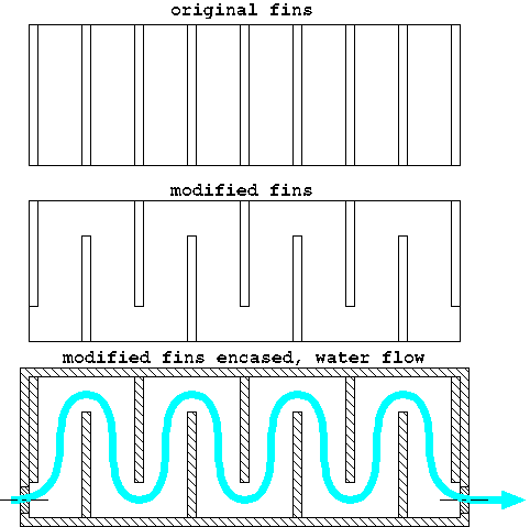
On the other hand, it might be easier to just modify the heatsink a bit, and use it for watercooling. I like this idea, because it gives me an easy way of getting a lot of surface area in the waterblock. I'd cut 1/2" off of each fin, alternating, then see if Dan will help me make a composite piece to seal it up. Something like this:
-
Audio
- May 15, 2004
-
Audio
My Alpine MRD-F752 amplifier died on me. Protection circuit kicks in as soon as it's powered up, even with nothing connected to the outputs. Sadly, it looks like it's time for a new amp.Whatever I decide to do here, I should finally do something about cooling, utilizing the trunk pressure release vents. I'd love to do watercooling, and I already have a 12V Eheim pump. The hard part is the waterblock. Can Dan make one out of composite for me?
Amp setups I'm considering...
Zapco 1000.4 and Zapco 500.1 ???? + $339.00 a/d/s P850.2 $700.00 a/d/s PQ30.2 $900.00 Phoenix Gold Xenon X100.4 + Phoenix Gold X400.1 $470.00 + $330.00 = $800.00 Alpine MRV-F540 + Alpine MRD-M300 $370 + $260.00 = $630.00 JL Audio 500/5 $620.00
-
Audio